
Conductive Silicone Tubing: Read the 10^6–10^10 Ω Range with Geometry in Mind
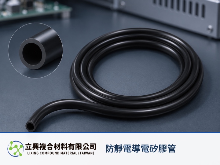
Conductive silicone tubing gives precision-electronics protection and industrial conductive sealing projects a defined starting point for an electrostatic-dissipation path. The official product page lists 10^6–10^10 Ω. Engineers and buyers should read that range together with tube length, hollow cross-section, measurement direction, and ASTM D257 conditions before turning a catalog value into an acceptance requirement.
A stated resistance range creates a practical sampling target
The official data lists an ohmic range of 10^6–10^10 Ω and identifies ASTM D257 as the test method. This gives conductive tubing projects a concrete point for sample discussions. The acceptance document should still identify specimen geometry, electrode placement, conditioning, and measurement direction so that supplier and incoming-inspection readings describe the same setup.
70 ± 5 Shore A supports routing and mechanical review
The tubing is listed at 70 ± 5 Shore A, with tensile strength of at least 5 MPa and elongation at break of 170%. These verified values help teams compare routing and handling requirements during sampling. They do not establish an allowable bend radius, installation strain, or service life without application-specific validation.
One equation explains why resistance changes with geometry
OpenStax College Physics gives R = ρL/A for a uniform material of constant cross-section. R is resistance in Ω, ρ is resistivity in Ω·m, L is current-path length in m, and A is effective cross-sectional area in m². A longer path raises resistance, while a larger area lowers it when material and conditions stay constant. Real silicone tubing is hollow, and filler distribution, temperature, contact resistance, electrode placement, and test direction can change the reading. The equation explains the principle; it does not replace ASTM D257 sample testing.
Put electrical and mechanical conditions on the same sample sheet
A useful sample definition records tube length, inner and outer diameter, electrode positions, conditioning, measurement direction, and the acceptance range. It can then pair those electrical conditions with 70 ± 5 Shore A hardness, tensile strength of at least 5 MPa, and 170% elongation at break. Shielding effectiveness, a specific grounding assembly, or an environmental sealing rating would require separate evidence and should not be inferred from resistance alone.
Build a repeatable dissipation condition for precision electronics
The black conductive silicone tube product data places resistance, hardness, and tensile behavior in one sourcing discussion. For precision-electronics protection and industrial conductive sealing, provide the operating length, inner and outer diameters, measurement direction, electrode arrangement, and environmental conditions with the sample request. Those details turn the 10^6–10^10 Ω range into a reproducible validation plan.
#ConductiveSiliconeTubing #ESD #StaticDissipation #PrecisionElectronics #IndustrialSealing