
G-TT-GY Thermal Silicone Tube Turns Coolant Routing into a Heat-Transfer Path
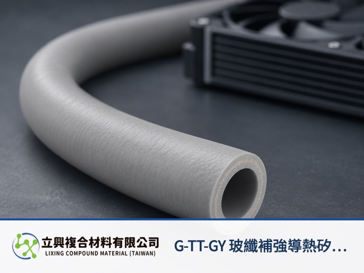
G-TT-GY Fiberglass-Reinforced Thermal Conductive Silicone Tube carries coolant while its 2 W/m·K wall participates in heat transfer. Engineers working on data centers, EV battery packs and power equipment can route an electrically insulating coolant line through constrained spaces, then verify system performance against flow, temperature rise and actual dimensions.
A conductive wall makes the flow path part of thermal design
The wall of G-TT-GY fiberglass-reinforced thermal silicone tubing has a listed thermal conductivity of 2 W/m·K. This creates a defined material path between the coolant and its surroundings. The value describes the material; wall thickness, contact, flow and external convection still govern the performance of a complete run.
Annular fiberglass reinforcement supports pressure and routing
One annular glass-fiber cloth layer sits in the middle of the tube wall to support dimensional stability and pressure resistance. The construction suits routes that need broad bends and layout flexibility. Bend radius, diameter and connection conditions still require confirmation on the intended sample.
Temperature and insulation data provide a starting point
The catalog lists an operating range of -40 to 200°C, UL 94 V-0 and electrical-insulation data. These values guide material selection; they do not certify an assembled cooling system to the same conditions. Buyers should confirm finished dimensions, tolerances, coolant compatibility and the applicable test setup.
Estimate coolant heat transport with an energy balance
The DOE heat-exchanger reference uses Qdot = mdot × cp × ΔT. Qdot is heat-transfer rate in W, mdot is mass flow rate in kg/s, cp is specific heat in J/(kg·K), and ΔT is the coolant outlet-to-inlet temperature difference in K. The model applies to single-phase, approximately steady flow with nearly constant specific heat. It omits wall contact resistance, external convection, local losses and pressure drop, so it is not a product performance guarantee. See the DOE Fundamentals Handbook: Heat Exchangers.
Send the full routing conditions with a sample request
Provide coolant type, target flow, inlet and outlet temperatures, tube diameter, wall thickness, total length, bend envelope and connection method. Catalog values are typical and require confirmation for the requested dimensions. The full product specifications covers a separate interface question and helps distinguish it from this coolant-flow decision.
Route coolant around real equipment constraints
For data centers, EV battery packs and power equipment that need a heat-conductive, electrically insulating coolant line, the 2 W/m·K wall and annular reinforcement provide a concrete sampling basis. Share flow, temperature and routing dimensions with Lixing to confirm a suitable specification and sample.