
Phase Change Thermal Pads from Solid Placement to Interface Wetting
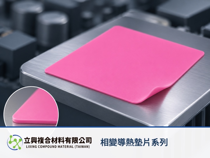
Phase change thermal pads give server and high-power-module interfaces a solid sheet for controlled die cutting and placement at room temperature, then soften from 45°C to 55°C to wet the contact surfaces. Thermal engineers can connect automated assembly with lower-resistance contact across one operating sequence, while checking placement temperature, transition range, service conditions and thermal cycling separately.
Solid handling keeps automated placement controlled
The LXPCM Phase Change Thermal Pad Series remains a solid sheet at room temperature and supports die cutting and automated placement. High-end electronics assembly can control the outline and location before the heat sink is fastened, reducing the boundary-control variables associated with applying a paste.
Interface wetting starts in the transition range
At 45°C to 55°C, the material progressively softens and wets the thermal interface, filling fine surface irregularities and air gaps. This behavior matters in CPUs, GPUs, telecom base stations and optical transceiver modules because the real contact condition between the heat source and heat sink contributes to interface temperature drop.
Service range and phase-change range answer different questions
The official product page lists an operating range of -40°C to 125°C and a phase-change range of 45°C to 55°C. The first states the published service boundaries. The second identifies where the interface state begins to change. Cold start, rated load and hot operation therefore need separate verification under their own contact conditions.
Catalog values are a comparison starting point
The official page lists thermal conductivity of 4 W/m·K, thermal impedance of 0.08 °C·in²/W, density of 2.8 g/cm³ and customizable thickness. ASTM D5470 is listed for thermal conductivity and ASTM D792 for density. A supplier report still needs sample thickness, pressure and test temperature beside the result; the thermal interface contact article provides the next context for contact-condition decisions.
Compare temperature points with thermal resistance
Area-normalized thermal resistance can be written as R'' = ΔT / q''. R'' is area-normalized thermal resistance in m²·K/W, ΔT is the interface temperature difference in K or °C, and q'' is heat flux in W/m². A NASA technical report on thermal contact resistance defines resistance using temperature difference, heat flux and area. Use this steady-state model when area, clamping and interface state are defined. It does not predict the phase transition, transient response or cycling life, and one catalog value cannot be extrapolated across -40°C to 125°C.
Send four operating inputs with a sample request
For an EV inverter, server or telecom power module, provide the actual contact area, target thickness, clamping method and temperature history from cold start to rated load. If thermal resistance will be compared, align test pressure, specimen thickness and test temperature so results from different conditions are not treated as equivalent.
Let the interface enter its working state with the device
Phase Change Thermal Pads support high-end electronics assembly as solid sheets, then provide dynamic interface filling for high-power modules and servers after warming. Put the transition range, service temperature, thickness and clamping conditions in one sample request to make subsequent measurement closer to the real duty cycle. Contact Lixing Composite Materials Co., Ltd. for sample and specification consultation.
#PhaseChangePad #ThermalManagement #InterfaceResistance #ServerCooling #PowerModules