
Custom-Sized Heat Dissipation Tube: Fit the Component and Preserve Assembly Space
A custom-sized heat dissipation tube can follow a power component's envelope while preserving room for the surrounding assembly. Start a sample request with the component's maximum envelope, permitted tube outside diameter and required sleeve length, then use inside diameter and wall thickness to define a testable sample condition. This gives engineering and procurement teams a clearer fit target than a single approximate tube diameter.
An inside-diameter range gives the fit discussion a defined starting point
The official Lixing page lists an inside-diameter range of 0.5–25 mm and states that dimensions can be customized for the application. The final ID still needs to reflect the maximum envelope and tolerance of the diode, transistor or sensing component. Review the official Heat Dissipation Tube specifications and applications before requesting a sample.
Defining wall thickness and OD together protects the space envelope
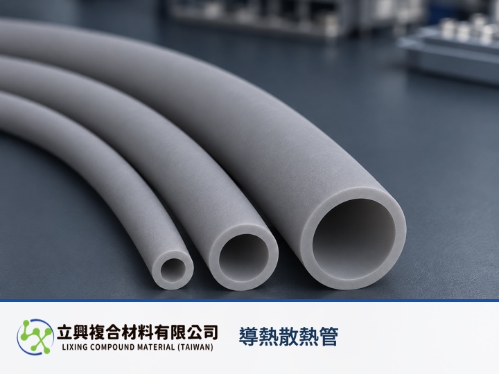
The product page lists wall-thickness options of 0.5 mm and 1.2 mm. Wall thickness changes the outside diameter, so available clearance around adjacent parts, the enclosure or a wiring channel belongs in the same request. The official image supports a grey, smooth matte tube with a round opening and a uniform visible wall; actual post-assembly contact still requires sample verification.
Two hardness options support different assembly discussions
The product page lists Shore A 50 and 70 hardness options and elongation of at least 150%. These values help engineers discuss insertion and shape accommodation, but they do not directly predict the installation force for a specific component. Supplying a component outline or maximum dimensions creates a more verifiable sample condition than asking only for a softer tube.
The product remains positioned for thermal protection and electrical insulation
The documented applications include jacketing and thermal protection for diodes, transistors, electronic sensing components and precision electrical devices. The page lists thermal conductivity of 0.8–1.0 W/m·K, dielectric strength above 4 kV and an operating-temperature range of -30 to +210°C. These are product-page material data; the final assembly still needs validation against component geometry, contact conditions and actual electrical requirements.
One geometry equation connects ID, wall and OD
The Swagelok Tube Fitter's Manual gives the tube relationship OD = ID + 2t. OD is outside diameter, ID is inside diameter, and t is one-side wall thickness; use one consistent unit such as mm. The relationship applies to nominal geometry for circular, concentric tubing with uniform wall thickness. It describes geometry only and does not predict assembly compression, tolerance stack-up, thermal expansion, contact resistance or dielectric performance.
Turn the request into a verifiable size condition
Provide the component's maximum envelope and tolerance, available external clearance, sleeve length, operating temperature and required electrical conditions. The supplier can then propose an ID, wall and hardness combination for sample checks covering insertion, position and clearance. Start with the Heat Dissipation Tube product page to request a sample and confirm customization.
#HeatDissipationTube #SiliconeTube #CustomSizing #PowerComponents #ThermalManagement