
How LXPCM Phase Change Pads Reduce Interface Thermal Resistance
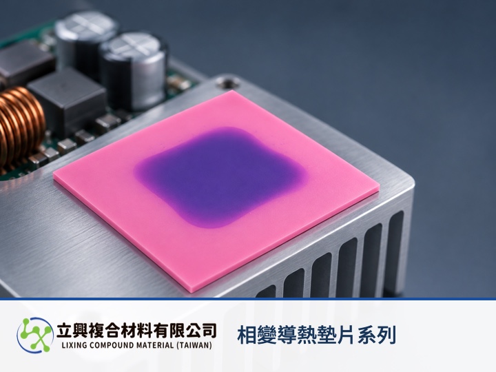
LXPCM Phase Change Thermal Pad Series suits designs that need lower component-to-heatsink interface resistance without giving up the handling of a solid sheet. It remains solid at room temperature, then progressively softens at 45°C to 55°C and wets fine surface irregularities. Engineers should hold thickness, contact area, mounting pressure and surface condition constant before comparing temperature difference and heat-transfer rate, because thermal conductivity alone does not describe the assembled interface.
A solid sheet supports controlled cutting and placement
The room-temperature solid form can be die-cut and placed by automated assembly. The official product page lists power modules, high-end electronic components, servers and automotive electronics as applications. Once the interface enters the 45°C to 55°C phase-change range, the material softens and wets the mating surfaces. This can reduce air gaps associated with microscopic irregularities, but it does not make every mounting condition equivalent.
Low resistance depends on bulk material and both contacts
The product page lists 4 W/m·K thermal conductivity tested by ASTM D5470 and 0.08 °C·in²/W thermal impedance. Conductivity describes heat transport through the material, while impedance is closer to an assembled interface result. Thickness, contact area, mounting pressure and surface roughness therefore need to be controlled when candidates are compared. The verified values and applications are available on the LXPCM Phase Change Thermal Pad product page.
Engineering equation: R = ΔT / Q
A NASA thermal-contact report defines thermal resistance as R = ΔT / Q. R is thermal resistance in K/W or °C/W, ΔT is the temperature difference across the heat-flow path in K or °C, and Q is the steady heat-transfer rate in W. At the same Q, a smaller ΔT corresponds to a lower R. Use the equation for steady-state comparisons with defined boundaries. It does not separate bulk resistance from the two contact resistances, and it cannot project one catalog value to another thickness or pressure. See the NASA Thermal Contact Conductance report.
Three verified benefits guide sample selection
Interface wetting addresses microscopic surface gaps
The official page states that LXPCM softens at 45°C to 55°C and fills fine surface irregularities. This makes the series relevant when contact resistance is the design concern. If the operating interface never reaches that range, the phase-change behavior should not be evaluated in the same way.
Sheet handling supports pre-cut placement
The solid sheet can be cut before assembly, helping define the coverage outline before the heatsink is mounted. Thickness is customizable, so a sample request should include heat-source dimensions, heatsink contact dimensions and the intended mounting condition.
The listed temperature range covers several electronics contexts
The official page lists an operating range of -40°C to 125°C and names power modules, servers and automotive electronics. A design review still needs component peak temperature, cycling conditions and assembly geometry; the range endpoints are not a substitute for system validation.
Send assembly conditions with the sample request
Provide contact dimensions, target thickness, mounting pressure, operating temperature and heat-source power, then compare candidates under the same conditions. After reviewing the Phase Change Thermal Pad Series specifications, contact Lixing for samples or specification consultation. The website does not offer online checkout.