
Custom Co-extruded Conductive Silicone Gasket Profiles: Sizing Compression to Your Groove
When the enclosure groove is already fixed, a co-extruded conductive silicone gasket can be made in a custom cross-section that fits it, so one extruded part handles both the EMI contact and the moisture seal. Before prototyping, check three things: groove depth and width, the compression ratio after fastening, and how much of the groove the profile fills. Then compare them with the material data on the co-extruded conductive silicone gasket product page and request samples with your groove drawing.
The profile follows your groove, not the other way round
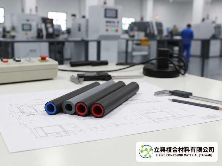
The product page states that custom cross-section profiles are available on request. Once a sheet-metal flange or die-cast housing has been tooled, changing the groove is expensive. Drawing the gasket around the existing groove lets the design team start from a drawing and discuss profile height, width and whether a hollow core is needed.
Conductive shell and sealing core in one extrusion
The outer layer is a nickel-graphite conductive material and the inner layer is a high-resilience non-conductive silicone, joined in a single co-extruded section. The shell forms the electrical path against the mating metal, while the core provides the moisture seal and recovery. The English product page adds that the extrusion process creates a strong bond between layers, which is intended to reduce delamination in the field.
Easier to compress than conventional conductive parts
According to the product page, this gasket is easier to compress and install than conventional conductive products. Hardness is listed as 65 ± 5 Shore A (GB 531-81), and compression set after 70 hours at 100°C is listed as ≤32% (ASTM D395), a useful reference when comparing how much recovery remains after long-term compression.
Material data ready for your specification sheet
The data table on the product page lists these typical values, which can be quoted with their reference standards:
- Volume resistivity ≤0.1 Ω·cm (MIL-G-83528)
- Continuous operating temperature -55 to 160°C
- Shielding effectiveness: 200 kHz H-field ≥50 dB, 100 MHz E-field 100 dB
- Shielding effectiveness: 2 GHz plane wave 90 dB, 10 GHz plane wave 80 dB
- Specific gravity 2.0 ± 0.25 (ASTM D792), tear strength 5 kN/m (ASTM D624)
These are material values under standard test conditions. In a real enclosure, shielding also depends on seam length, compression state and contact surface finish, so verify on the assembled part.
Suited to telecom housings, outdoor cabinets and instrument enclosures
The product page lists telecommunications equipment and precision electronic instruments among its uses, and notes the nickel-graphite coating's resistance to mould and salt spray for outdoor service. Typical locations are door-frame grooves on outdoor telecom cabinets and the seam between an instrument panel and its housing. If contact resistance is the main question at your seam, continue with our note on low-resistance contact with the nickel-graphite gasket.
Check profile size with compression ratio and gland fill
A custom profile can be sized first with two ratios widely used in seal design:
C(%) = (H0 - Hg) / H0 × 100; F(%) = Ap / (Hg × W) × 100
- C: compression ratio, %
- H0: free height of the gasket in the compression direction, mm
- Hg: groove depth (assembled compressed height), mm
- F: gland fill, %
- Ap: solid cross-sectional area of the gasket profile (hollow core excluded), mm²
- W: groove width, mm
Too little compression and the nickel-graphite shell may not make enough contact. Too much fill and the squeezed silicone has nowhere to go, so the cover may not close flat. The Freudenberg-NOK O-Ring Design Quick Reference Guide presents both formulas for O-rings and treats elastomers as essentially incompressible; it also advises leaving gland fill margin for thermal expansion and tolerance stack-up.
Limitations: The source formulas are written for O-rings and do not address gland angle; hollow or shaped profiles deform differently from a solid round section, so the guide's O-ring ranges are not specifications for this product. Thermal expansion, tolerance stack-up and flange bowing between fasteners change real compression and must be confirmed on prototypes. The formulas are engineering estimates, not a compression specification or performance guarantee for this product.
What to send with your enquiry
- Groove drawing with depth, width and corner radius
- Fastening method and screw spacing
- Operating temperature range and the frequency band to be shielded
- Whether a hollow profile is needed, plus the mating metal and its finish
With these details, contact Lixing through the product page to request samples or a specification review, or email yw@zh-lx.com. Fit the prototype into the real enclosure, measure contact and sealing after compression, then freeze the profile.
Tags: #ConductiveSilicone #EMIShielding #NickelGraphite #CustomGasket #EnclosureSealing