
Aluminum Foil Thermal Tape for Heat and EMI Boundaries
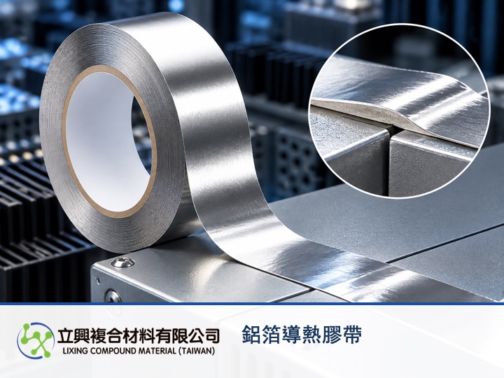
When an electronics assembly leaves very little vertical space, H-TT-AL aluminum foil thermal conductive tape offers a continuous silver foil tape that can support bonding and a thermal path while preserving a metal layer for a local EMI boundary. For design engineers and buyers, the useful question is not simply whether foil is present, but whether the installed tape forms a continuous boundary across real seams, overlaps and grounding points.
A thin tape format keeps heat and EMI functions compact
The official product page lists a total thickness of 0.100 ± 0.005 mm, comprising 0.060 ± 0.003 mm face stock and 0.040 ± 0.003 mm adhesive. This thin roll format suits surface-bonded layouts that cannot accept much additional stack height. These dimensions and tolerances come from the official H-TT-AL specification page.
Continuous aluminum foil provides a usable local EMI boundary
The product page states that the metal carrier provides a degree of EMI shielding. At assembly level, foil continuity, overlap width, edge gaps and the grounding path determine how useful that boundary becomes. H-TT-AL therefore fits applications that must consider heat spreading and a local EMI boundary together, but no shielding value in dB should be claimed without a stated frequency and test configuration.
An adhesive roll integrates into localized assembly paths
The uniform adhesive layer supports localized attachment to metal and plastic substrates. The official page lists loop tack of 0.6 kg/25mm and adhesion to stainless steel of 1.5 kg/25mm. These are published product-page values, not guarantees for every surface treatment or environment; sampling should still account for cleanliness, curvature and peel stress at edges.
Published thermal properties let the tape carry a heat-transfer role
The official page lists thermal conductivity of 0.45 W/(m·K) and an operating temperature range from -30°C to 150°C. It names LEDs, notebook computers, touch panels and power-conversion equipment as applications. This makes the tape relevant where bonding, heat transfer and a metal boundary must share a thin material, although real thermal resistance still depends on contact surfaces, pressure and the assembly stack.
How should shielding effectiveness be interpreted?
As an engineering measurement model, electric-field shielding effectiveness can be written as SE(dB) = 20 log10(|E_without / E_with|). SE is shielding effectiveness in dB; E_without is electric-field strength without the shield in V/m; E_with is electric-field strength at the same position under the same conditions with the shield in V/m. The NIST study of shielding-effectiveness measurements explains that field region, antennas, geometry and material parameters affect the result. This equation explains measurement logic; it is not an H-TT-AL tested specification. A dB value cannot be inferred from foil alone without fixing frequency, polarization, distance, apertures, seams and grounding.
Put overlaps, seams and grounding into the sample definition
For specification support or samples, provide the substrate, tape width or die-cut geometry, operating temperature, frequency range of concern, overlap and grounding layout. Lixing Composite Materials Co., Ltd. does not offer online checkout; contact yw@zh-lx.com for specification consultation and sample requirements.
#AluminumFoilTape #EMI #ThermalMaterials #ElectronicsCooling #IndustrialTape