
Fiberglass Thermal Tape with 5 kV Withstand Voltage: Thin 0.095 mm Insulation That Still Moves Heat
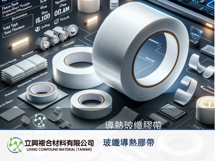
In power modules and LED boards the heat sink often sits right against live components: heat has to cross, voltage must not. H-GT-WH fiberglass thermal conductive tape answers both with one white layer only 0.095 mm thick in total: the product page lists a 5 kV withstand voltage for the insulation barrier and a thermal conductivity of 0.35 W/(m·K), so you add electrical isolation between heat source and heat sink without stacking a thick pad. Confirm that the 5 kV test conditions match your working voltage and creepage design, and you can judge quickly whether this fiberglass tape fits.
Benefit 1: 5 kV withstand voltage in a 0.095 mm layer
The specification table lists a 0.050 mm face stock, a 0.045 mm adhesive layer and a total thickness of 0.095 ± 0.005 mm (the transparent PET liner peeled off before use is not included), with a withstand voltage of 5 kV. In crowded power boards and lighting modules, that means you can place an insulating layer between live parts and a metal heat sink without noticeably raising the heat sink.
Benefit 2: Isolation that keeps the heat path open
Most insulators also slow heat down, and the thicker the layer, the longer the path. This tape lists a thermal conductivity of 0.35 W/(m·K) and sits as a thin layer between heat source and heat sink, which suits designs that need insulation plus fixing without a thicker interface. For how a thin layer affects thermal impedance, see our fiberglass thermal tape interface contact and thermal impedance analysis.
Benefit 3: A fiberglass carrier that keeps the thin layer intact
According to the product page, the fiberglass carrier gives the tape good structural strength and tensile resistance, making it suitable for automated lamination. If an insulating film tears or wrinkles during application, it thins locally or leaves gaps; a supported thin layer is better placed to keep its thickness uniform, and thickness is one of the variables in the formula below that sets the voltage a layer can hold.
Benefit 4: Adhesion that keeps insulation where it belongs
The uniform adhesive layer lists a loop tack of 0.5 kg/25mm and a holding power of 24 H, with an operating temperature range of -20°C to 120°C. If the tape lifts at an edge, the edge of a live component can end up uncovered; stable adhesion is what keeps the isolation in place.
Where it fits
The product page lists thermal fixing between power conversion equipment and heat sinks, high-power LED modules and fixtures, cooling parts inside notebooks and tablets, and heat management for touch panels and LCD modules. In each of these positions, its job is to add a layer with a stated withstand voltage between the heat source and the cooling surface.
Engineering note: why thickness and withstand voltage go together
The parallel-plate idealization is V_max = E_c × d: V_max is the maximum voltage an insulating layer can withstand under a uniform field (kV), E_c is the dielectric strength of the material, the critical field at which breakdown begins (kV/mm), and d is the insulation thickness between the electrodes (mm). Source: OpenStax University Physics Volume 2, 8.5 Molecular Model of a Dielectric. It shows that the same material withstands less voltage when it is thinner, so wrinkles, scratches or trapped bubbles that thin the layer locally deserve attention. The model assumes a uniform field and a homogeneous material and ignores edge field concentration, temperature and humidity, partial discharge in voids and test duration; it is not a product specification and cannot be used to derive this tape's dielectric strength.
Selection note: read 5 kV against your own conditions
The product page does not state the test method, AC or DC, test duration or specimen thickness behind the 5 kV figure, so request those conditions before qualification and compare them with your working voltage and safety margin. The tape insulates through its thickness; creepage and clearance along surfaces still have to follow the applicable safety standard, and sharp burrs or solder points should be removed so they cannot pierce the thin layer.
Planning a power supply or lighting design?
Tell us the heat source, heat sink material, working voltage and application method, and we will help confirm width, die-cut shape and documentation. See the H-GT-WH fiberglass thermal conductive tape specifications and sample request, or email yw@zh-lx.com to contact us.
#FiberglassTape #ThermalTape #ElectricalInsulation #PowerSupplyCooling #LEDCooling